Simulation
Pauline can emulate a floppy disk drive on a real machine via the floppy disk drive ribbon cable. You can simulate one or more virtual drives and thus test your originals dumps.
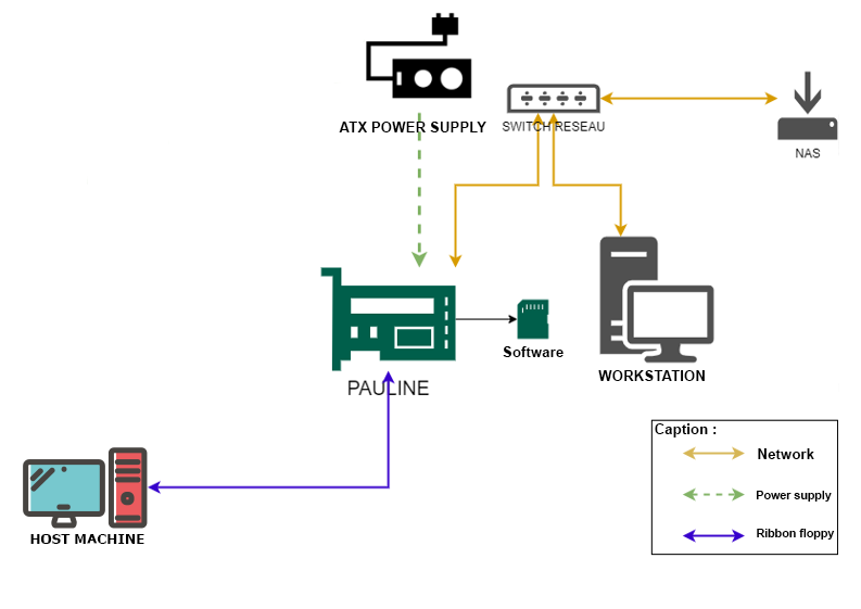
Depending on the host machine, we can replace Pauline's external power supply by the host's +5V. However, be careful about the stability and power delivered by the host machine's power supply, which could prove to be of insufficient quality. The main power supply of the DE10 has an overvoltage protection which, in theory, should disconnect the DE10-nano if the input is greater than 5.4V. The power consumption is about 1A - 1.2A (information given for information purposes, please take maximum care not to damage the components).
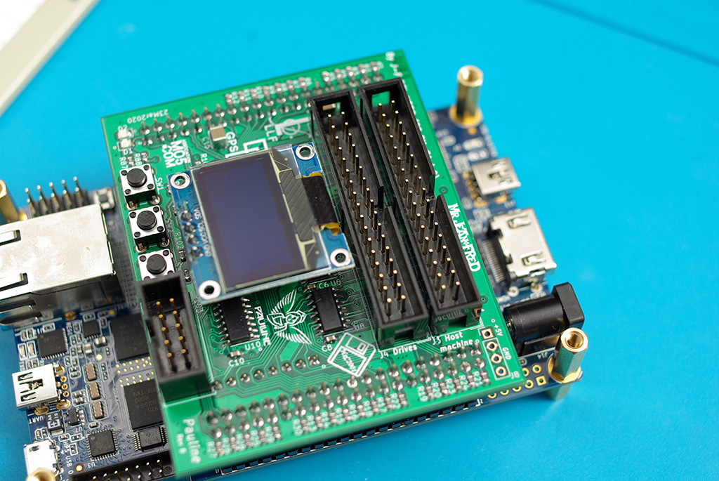
Connecting Pauline to Host
Locate the "Host machine" connector, connect the floppy disk to this connector.
Connect Pauline as a real floppy drive on the host machine.
Reminder:
After the "twist" on the ribbon cable => Pauline will be in Drive A (PC Drive),
before the twist => Pauline will be in Drive B (PC Drive)
See appendices for some information on floppy ribbon cable.
Disclaimer
The simulation mode is subject to change in future firmware updates (web interface integration is planned, for instance).
For the moment, this mode is only accessible from the command line ( through SSH).
Shugart and PC floppy drive simulation is currently functional.
Pin 02, pin 34 and drive selection are configured differently between the "Shugart" interface and the "PC" interface:
Density Select in pin 02 for "PC" but Disk Change Detect in Shugart mode
Disk Changed on pin 34 for "PC" but Drive Ready in Shugart mode
DRVSB (Pin 12) for "PC" and SEL0 (Pin 10) for the Shugart
We will use the same motor command (pin 16) for both interfaces.
Operation
Image location folder home/pauline/Drives_Simulation/
To facilitate the simulation mode usage, it is advisable to place the image files of the disks to be loaded into this folder.
On Windows, you can use Putty, as well as MobaXterm which allows you to save your login/password and especially to record macros which is very useful for the simulation mode.
Step 1: convert the image file to stream hfe
Either with HxCFloppyEmulator Export disk / Save As type: HFE file (stream - Exprimental) (*.hfe)
or
in the command line:
hxcfe -conv:HXC_STREAMHFE -finput:"XXXX.img"
The .hfe extension can be used for another purpose (archiving, ...), you will have to check if the XXXX.hfe file has a "HxC_Stream_Image" header "48 78 43 5F 53 74 72 65 61 6D 5F 49 6D 61 67 65".
If the .hfe file has a different header, the file cannot be loaded.
Step 2: load the image into memory and activating the PC interface simulation:
Simulating PC Drive A: 5,25" DD
pauline -reset -load:"XXXX.hfe" -drive:0 -pin34mode:6 -pin02mode:0 -selsrc:9 -motsrc:12 -led1src:17 -led2src:24 -enabledrive
Simulating PC Drive A: 3,5" DD
pauline -reset -load:"DOS622 - 720K_80.hfe" -drive:0 -pin34mode:6 -pin02mode:0 -selsrc:9 -motsrc:12 -led1src:17 -led2src:24 -enabledrive
Simulating PC Drive A: 5,25" HD
pauline -reset -load:"XXXX.hfe" -drive:0 -pin34mode:6 -pin02mode:1 -selsrc:9 -motsrc:12 -led1src:17 -led2src:24 -enabledrive
Simulating PC Drive A: 3,5" HD
pauline -reset -load:"DOS622 - 144M_80.hfe" -drive:0 -pin34mode:6 -pin02mode:1 -selsrc:9 -motsrc:12 -led1src:17 -led2src:24 -enabledrive
Simulating PC Drive A: no disk (for booting without POST error code "A: Drive Error")
pauline -reset -drive:0 -pin34mode:6 -pin02mode:1 -selsrc:9 -motsrc:12 -enabledrive -led1src:17 -led2src:24
The command Pauline -help will give an overview of the available features.
Reminder
Drive Simulation select lines ID (-selsrc & -motsrc ID):
  0 : Always deasserted
  1 : Always asserted
  8 : SEL0/MOTEA  (Pin 10)
  9 : SEL1/DRVSB  (Pin 12)
  10: SEL2/DRVSA  (Pin 14)
  11: SEL3        (Pin 6)
  12: MTRON/MOTEB (Pin 16)
  13: EXTERNAL IO (J5 - Pin 4)

Drive Simulation status lines ID (-pin02mode & -pin34mode ID):
  0 : Low state
  1 : High state
  2 : nReady
  3 : Ready
  4 : nDensity
  5 : Density
  6 : nDiskChange (mode 1 : Head step clear)
  7 : DiskChange  (mode 1 : Head step clear)
  8 : nDiskChange (mode 2 : Head step clear + timer/timeout clear)
  9 : DiskChange  (mode 2 : Head step clear + timer/timeout clear)
  10: nDiskChange (mode 3 : timer/timeout clear)
  11: DiskChange  (mode 3 : timer/timeout clear)
  12: nDiskChange (mode 4 : floppy_dc_reset input clear)
  13: DiskChange  (mode 4 : floppy_dc_reset input clear)

Signal input mux (-led1src & -led2src ID):
  0 : LED gpio register
  1 : Floppy pin 10 drive 0 selection output
  2 : Floppy pin 12 drive 1 selection output
  3 : Floppy pin 14 drive 2 selection output
  4 : Floppy pin 6  drive 3 selection output
  5 : Floppy pin 16 Motor on output
  6 : Floppy step output
  7 : Floppy dir output
  8 : Floppy side1 output
  9 : Floppy index input
 10 : Floppy pin 2 input
 11 : Floppy pin 34 input
 12 : Floppy write protect input
 13 : Floppy data input
 14 : Floppy write gate output
 15 : Floppy write data output
 16 : Host pin 10 / sel 0 input
 17 : Host pin 12 / sel 1 input
 18 : Host pin 14 / sel 2 input
 19 : Host pin 16 / sel 3 input
 20 : Host pin 6  / mot on input
 21 : Host step input
 22 : Host dir input
 23 : Host side1 input
 24 : Host write gate input
 25 : Host write data input
 26 : IO input 0
 27 : IO input 1
 28 : IO input 2
 29 : IO input 3
 30 : IO input 4
 31 : IO input 5
For PC: -pin34mode:6 and pin02mode:0 or pin02mode:1 according to the disk's density.
It is via these 2 signals that the computer knows about disk change and density (DD or HD).
Drive Before the Twist Sees
SEL0/MOTEA  (Pin 10)
SEL1/DRVSB  (Pin 12)
SEL2/DRVSA  (Pin 14)
MTRON/MOTEB (Pin 16)

Drive After the Twist Sees
MTRON/MOTEB  (Pin 10)
SEL2/DRVSA  (Pin 12)
SEL1/DRVSB  (Pin 14)
SEL0/MOTEA (Pin 16)
Warning: the floppy drive choice in the Bios parameters of the host machine is essential.
Special commands
-doublestep => force doublestep for 5,25" floppy 360K if HD drive (1,2 MB 5,25") set in Bios parameter. Only use in case of problems with the 5.25" floppy disk simulation.
-writeprotectdrive:[0/1] => drive simulation write protect (0 or 1)
pauline -reset -drive:0 -pin34mode:6 -pin02mode:1 -selsrc:9 -motsrc:12 -enabledrive -led1src:17 -led2src:24 => Enable or eject disk PC drive, can be recorded as a macro in MobaXterm
Shugart interface simulation
pauline -reset -load:"XXXX.hfe" -drive:0 -pin34mode:2 -pin02mode:6 -selsrc:8 -motsrc:12 -led1src:17 -led2src:24 -enabledrive
LED Activation
Green LED pin 12 drive A or B / Red LED pin Host write gate input
-led1src:17 -led2src:24 for the activation of the led works in PC interface simulation but remains to be validated in Shugart simulation.
Activating other drives in Shugart interface
pauline -load:"XXXX.hfe" -drive:1 -pin34mode:2 -pin02mode:6 -selsrc:9 -motsrc:12 -led1src:17 -led2src:24 -enabledrive
to simulate drive "B"
For loading, just change the drive parameter and the selection sources. Do not do a -reset for the loading of other drives.
Once activated the simulation is carried out in hardware: the Pauline software plays no role after loading.
To save the contents of the disk in drive A
Warning: When writing, it is necessary to remember to save the image before turning off the card
pauline -save:"XXXX.hfe" -drive:0
Conclusion
This 5 minute video shows the information presented in this documentation
